|
|
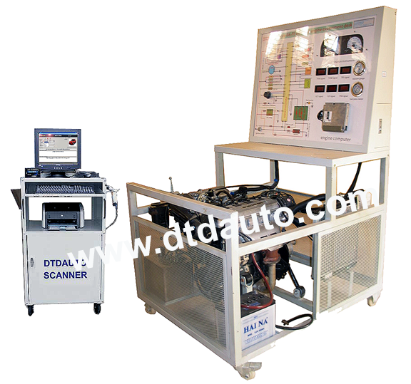
OBD-II MULTI-POINT INJECTION & IGNITION ENGINE
Model EFI-MP-ENGINE-07 |
||||||||||||
 |
|||||||||||||
|
● Product code: ET2016 ● Origin: DTDAUTO ● Availability: In stock ● Rate: (Only support for Windows operating system) |
|||||||||||||
| ● OVERVIEW | |||||||||||||
| Multi-Point injection and ignition system, this trainer offers a complete range of experiments on one of the most advanced electronic control systems for injection and ignition. It is use in four-cylinder engines with multi-point intermittent fuel injection. The system includes an electronic unit that detects the signals from the various sensors and offers an integrated control of both the ignition and fuel supply. | |||||||||||||
 OBD-II Multi-point Injection & Ignition Engine |
|||||||||||||
| ● FEATURES | |||||||||||||
|
1.Toyota Camry engine of model 2.4 or 3.0 is completed (Model 1NZ-FE
or 1ZZ-FF or 2ZZ-FE)
2. Motor-driven pump and its driving relay 3. In-line filter with pulsation dampening 4. Double Lambda sensor for reducing pollution and controlling the catalytic converter 5. 4 injectors with manifold of transparent plexiglass 6. Fuel recovery pipe 7. Solenoid valve for recalculating fuels vapors 8. Sensor for the pressure of intake air with its own simulator 9. Sensor for the temperature of the engine with its own simulator 10. Potentiometer of the accelerator pedal for setting the engine load 11. Motor-driven throttle valve for the automatic control of the air intake in the engine collector 12. Ignition key with locking system 13.Electronic control unit for a good operation of the system 14. Body computer for controlling the CAN network and the diagnostic line via OBD connector 15. Complete dashboard connected via multiplex CAN network 16. 4 spark plugs 17. Static ignition coil 18. Protection against high voltage and access for current clampsomplete dashboard connected via multiplex CAN network 19. Key for selecting the air-conditioning unit 20. Simulator of the safety pressure switch of the refrigerant R134a 21. Most advanced gasoline injection and ignition systems for motor vehicles complying with antipollution standards for the following functions 22. Analysis of the control of injection according to the oxygen sensors before and after the catalytic converter 23. Analyzing the control of ignition angle 24. Checking the conditions for the fuel cut-off 25. Analyzing the waveform of the signal enabling the motor-driven throttle valve 26. Analyzing the physical line of the CAN bus between control unit 27. Microprocessor faults simulators, especially designed to enable the Teacher to inset various types of faults in the system and then to assess the troubleshooting processes carried out by the students with their proper instruments. The system can restart its right operation only after the student has typed the code of the faulty component using the same simulator. 28. Test points on all the connections of the electric components, for a thorough monitoring of the system. 29. Computer connection RS 232 serial interface 30. Trainer power supply: 220 V-50 Hz with magneto thermal differential switch with warning light and emergency stop push-button 31. Trainer operating voltage 12 VDC, generated by a battery and battery charger 32. Trainer fitted with castors and a working top with key-locked drawer. 33. Structure in steel sections painted with epoxy paints. 34. Exhaustive textbook in English 35. Diagnostic tester (Vietnamese and English). Professional PC based for faults finding can be used for: reading and display engine parameters, reading and display faults, erasing memorized faults, activation of actuators 36. Interactive software SW can be used by a PC (excluded) connected to the trainer via a suitable serial interface 37. Computer, control software and oscilloscope is included as picture above |
|||||||||||||
 Software interface |
|||||||||||||
| ● GENERAL FEATURES | |||||||||||||
| Power supply:
- The fuel for Engine - 220 V - 50 Hz for operation of Computer and Oscilloscope Operating voltage: - Battery 12 V/35A, charge by internal power supply, with electronic protection against overloads and short-circuits. - The equipment is provide with wheels and includes a working top with key-locked drawer. - The structure is of steel sections painted with durable epoxy paints. Dimensions: - 1100x1000x1200 mm. Course books: The Trainer comes with a course book, which includes: – A section dedicated to the theoretical treatment of the topics and to a description of the circuit or component – A section which acts as a guide to the learner for the practical experiments and for carrying out measurements, adjustments and calibrations of electrical circuits and electronic devices – A section on fault finding the programmed faults |
|||||||||||||
| ● LEARNING OBJECTIVESN | |||||||||||||
| Adjustment of the ignition angle, carried out with a stroboscopic lamp in relation to the: - Engine speed Absolute pressure in intake manifold – Position of butterfly valve – Engine temperature – Battery voltage Analysis of the control of injection times (with oscilloscope or diagnostic tester) in relation to the: – Engine speed – Absolute pressure in intake manifold – Temperature of the intake air – Engine temperature – Battery voltage – Lambda factor Analysis of the waveform of the actuator-driving signal in constant idling with the oscilloscope Analysis of the waveform of the signal coming from the speed sensor with the oscilloscope Checking the conditions for cut-off at the maximum number of engine speed Analysis of faults, irregularities, and operational defects: - Insertion of non destructive faults (cut-off, short circuits, contact resistances, etc.) by means of the microprocessor system of fault insertion - Fault-finding methods with traditional instruments (millimeters, oscilloscope, etc.) - Data collection and reading, signaling of malfunctions, fault location by guided diagnosis and information upon operator’s request, given through diagnostic tester (Tester is a computer based) |
|||||||||||||
| ● RELEVANT DOCUMENTS | |||||||||||||
|
|||||||||||||